Journals > > Topics > Optical Design and Fabrication
Optical Design and Fabrication|739 Article(s)
Optical System Design and Athermalization of Telephoto Lens
Lizhi Zhang, Qiuping Lu, Fanlin Duan, Xing Dai, and Dayong Qiao
ObjectiveThe actual working environment of vehicle-mounted LiDAR is complex, including seasonal long-time limit temperature and rapid changes in indoor and outdoor high and low temperatures. These temperature variations possibly change the internal optics and structure of the lens, which results in image plane drift and reduces imaging quality. For telephoto lenses, the image plane drift can be more obvious with the ambient temperature changes. The current passive athermalization design method has the problems of complex structure and large volume caused by multi-layer lens barrels, or the introduction of diffractive elements and aspheric lenses to increase the production cost, and the narrow temperature range of thermal-free, which is difficult to adapt to the practical applications in the complex environment of vehicle-mounted LiDAR. Therefore, it is necessary to reduce the image plane temperature drift and improve the environmental adaptability of telephoto lenses with an advanced athermal design method.MethodsThe telephoto lens which can accurately capture distant targets and magnify the details is integrated with a line array detector to improve the resolution. Meanwhile, based on the fact that the total length of the optical system of the telephoto structure is smaller than the focal length, the volume of the telephoto receiving optical system is compressed to a certain extent to realize the requirements of lightweight miniaturization and high resolution of the vehicle-mounted LiDAR. Aiming at the problem that the telephoto lens is susceptible to temperature, we improve the two-group compensation design method of the passive optical and mechanical athermalization to maximally offset the optical focal length change of the optical parts from the thermal difference brought by thermal expansion and contraction of the structural parts, and to reduce the image plane drift, thus realizing the athermalization of the telephoto lens. Finally, the image plane drift of the as-designed lens is less than the depth of focus over a wide temperature variation range from -40 to 100 ℃. This is conducive to ensuring the imaging quality of the lens, and the designed structure has a simple preparation process and is easy to engineer and produce.Results and DiscussionsDifferent combinations of optical materials and optical focal length distributions are determined, structural components of different thermal expansion coefficients (TCEs) are matched, and the thermal difference of the optical system compensates for each other, with the system athermalization design achieved. Without the thermal expansion and contraction of the barrel holder taken into account, the focal shift of the lens with temperature change is always minimized and the image plane drift is 0.075 mm when the temperature increases to 100 ℃ (Fig. 7). The thermal expansion and contraction of the barrel holder is considered as a material to compensate for thermal aberration to make the sensor detecting surface always in the image plane. In the wide temperature range from -40 to 100 ℃, with the temperature change, the receiving optical system obtained from the selected optics and structural component materials has almost no significant focal shift, even when the temperature is as high as 100 ℃, and meanwhile the amount of focal shift is only 0.021 mm, smaller than its depth of focus at room temperature (0.074 mm), and the field curvature and distortion of this optical system have small changes (Fig. 8). The MTF at 30 lp/mm is all larger than 0.5 for each field of view (FOV), and the focal plane shifts are all small, which indicates that the designed lenses can maintain sound image quality over a wide range of temperatures from -40 to 100 ℃ (Figs. 9 and 10). The diffuse spot radius in the full FOV is smaller than 7 μm, which reveals that the focal shift of the lens is little affected by temperature (Fig. 11). The results of photographing vehicles traveling on the road show clear imaging of the vehicles and obvious feature areas such as the outer contours of the vehicles (Fig. 14). The above results prove that the imaging quality and temperature adaptability of the lens can be guaranteed by the above athermalization design to compensate the system thermal difference.ConclusionsWe employ the telephoto lens with a long focal length and small FOV to subdivide the scanning area and integrate a line array detector to achieve an image-level imaging effect. Based on the characteristic that the total length of the optical system of telephoto structure is smaller than the focal length, a receiving optical system with a telephoto ratio of 0.38 is designed, which has a smaller lens length and lower cost and meets the requirements of vehicle-mounted LiDAR in terms of high resolution, light weight, and small size. Given the large temperature difference in the working environment of vehicle-mounted LiDAR and the image plane drift of the telephoto lens, a passive optical and mechanical athermalization is implemented to confirm the reasonable combination of multi-plane spherical glass lens and structural components. Finally, a four-piece telephoto lens optical system with a simple structure and a focal shift of 0.021 mm less than the depth of focus of 0.074 mm over a wide temperature range from -40 to 100 ℃ is designed. The MTF of each FOV at 30 lp/mm is larger than 0.5 and the diffuse spot radius in the full FOV is smaller than 7 μm. The vehicle imaging is clear, and the outer contour of the vehicle and other characteristics of the area are obvious, which achieves athermalization and shows favorable environmental adaptability. ObjectiveThe actual working environment of vehicle-mounted LiDAR is complex, including seasonal long-time limit temperature and rapid changes in indoor and outdoor high and low temperatures. These temperature variations possibly change the internal optics and structure of the lens, which results in image plane drift and reduces imaging quality. For telephoto lenses, the image plane drift can be more obvious with the ambient temperature changes. The current passive athermalization design method has the problems of complex structure and large volume caused by multi-layer lens barrels, or the introduction of diffractive elements and aspheric lenses to increase the production cost, and the narrow temperature range of thermal-free, which is difficult to adapt to the practical applications in the complex environment of vehicle-mounted LiDAR. Therefore, it is necessary to reduce the image plane temperature drift and improve the environmental adaptability of telephoto lenses with an advanced athermal design method.MethodsThe telephoto lens which can accurately capture distant targets and magnify the details is integrated with a line array detector to improve the resolution. Meanwhile, based on the fact that the total length of the optical system of the telephoto structure is smaller than the focal length, the volume of the telephoto receiving optical system is compressed to a certain extent to realize the requirements of lightweight miniaturization and high resolution of the vehicle-mounted LiDAR. Aiming at the problem that the telephoto lens is susceptible to temperature, we improve the two-group compensation design method of the passive optical and mechanical athermalization to maximally offset the optical focal length change of the optical parts from the thermal difference brought by thermal expansion and contraction of the structural parts, and to reduce the image plane drift, thus realizing the athermalization of the telephoto lens. Finally, the image plane drift of the as-designed lens is less than the depth of focus over a wide temperature variation range from -40 to 100 ℃. This is conducive to ensuring the imaging quality of the lens, and the designed structure has a simple preparation process and is easy to engineer and produce.Results and DiscussionsDifferent combinations of optical materials and optical focal length distributions are determined, structural components of different thermal expansion coefficients (TCEs) are matched, and the thermal difference of the optical system compensates for each other, with the system athermalization design achieved. Without the thermal expansion and contraction of the barrel holder taken into account, the focal shift of the lens with temperature change is always minimized and the image plane drift is 0.075 mm when the temperature increases to 100 ℃ (Fig. 7). The thermal expansion and contraction of the barrel holder is considered as a material to compensate for thermal aberration to make the sensor detecting surface always in the image plane. In the wide temperature range from -40 to 100 ℃, with the temperature change, the receiving optical system obtained from the selected optics and structural component materials has almost no significant focal shift, even when the temperature is as high as 100 ℃, and meanwhile the amount of focal shift is only 0.021 mm, smaller than its depth of focus at room temperature (0.074 mm), and the field curvature and distortion of this optical system have small changes (Fig. 8). The MTF at 30 lp/mm is all larger than 0.5 for each field of view (FOV), and the focal plane shifts are all small, which indicates that the designed lenses can maintain sound image quality over a wide range of temperatures from -40 to 100 ℃ (Figs. 9 and 10). The diffuse spot radius in the full FOV is smaller than 7 μm, which reveals that the focal shift of the lens is little affected by temperature (Fig. 11). The results of photographing vehicles traveling on the road show clear imaging of the vehicles and obvious feature areas such as the outer contours of the vehicles (Fig. 14). The above results prove that the imaging quality and temperature adaptability of the lens can be guaranteed by the above athermalization design to compensate the system thermal difference.ConclusionsWe employ the telephoto lens with a long focal length and small FOV to subdivide the scanning area and integrate a line array detector to achieve an image-level imaging effect. Based on the characteristic that the total length of the optical system of telephoto structure is smaller than the focal length, a receiving optical system with a telephoto ratio of 0.38 is designed, which has a smaller lens length and lower cost and meets the requirements of vehicle-mounted LiDAR in terms of high resolution, light weight, and small size. Given the large temperature difference in the working environment of vehicle-mounted LiDAR and the image plane drift of the telephoto lens, a passive optical and mechanical athermalization is implemented to confirm the reasonable combination of multi-plane spherical glass lens and structural components. Finally, a four-piece telephoto lens optical system with a simple structure and a focal shift of 0.021 mm less than the depth of focus of 0.074 mm over a wide temperature range from -40 to 100 ℃ is designed. The MTF of each FOV at 30 lp/mm is larger than 0.5 and the diffuse spot radius in the full FOV is smaller than 7 μm. The vehicle imaging is clear, and the outer contour of the vehicle and other characteristics of the area are obvious, which achieves athermalization and shows favorable environmental adaptability.
Acta Optica Sinica
- Publication Date: Apr. 25, 2024
- Vol. 44, Issue 8, 0822004 (2024)

Optimization Design of Progressive Corridor of Freeform Progressive Addition Lenses
Xin Zhang, Huazhong Xiang, Lefei Ma, Zexi Zheng, Jiabi Chen, Cheng Wang, Dawei Zhang, and Songlin Zhuang
ObjectiveA freeform progressive addition lens (PAL) is an optical lens composed of different optical powers, with a curvature that is not constant. It can achieve smooth focusing within a range of focal distances, from distant to near, providing a more natural adjustment for users. This type of lens fully meets both physiological and psychological needs, making it increasingly favored by the middle-aged and presbyopic population. The design of the meridional power distribution plays a crucial role in the astigmatic distribution, the lens' distance and near vision area, the width of the corridor, and the astigmatic gradient, all of which are essential for the wearer's comfort. The channel width of the lens is closely related to the design of meridional power, contour line distribution, and sagittal height surface profile. Lenses with a wide channel design exhibit lower image distortion, chromatic aberration, and spherical aberration. Moreover, they also feature smoother transition zones, reducing the adaptation period, and offering a more accurate and natural visual experience while minimizing eye fatigue and dizziness. The current design of meridional power does not adequately consider its impact on the overall channel width, and there is a lack of efforts to broaden the channel width. This results in lenses having a relatively high level of astigmatism within a single pupil size. Therefore, we propose a new meridional power distribution based on cumulative distribution functions and analyze the curvature of the function's impact on the width of the image dispersion center. Additionally, the overall sagittal surface shape overlay and the reduction of meridional power distribution curvature are employed to increase the channel width of progressive addition lenses.MethodsTo widen the progressive channel of progressive addition lenses, we propose a novel approach. Firstly, a method utilizing the cumulative distribution function is introduced for designing the meridional power distribution, and a comparative analysis is conducted with the commonly used octave polynomial function and trigonometric function. Subsequently, we superimpose sagittal height surface profiles calculated from different channel lengths of meridional power and contour lines to achieve the optimization of channel width, facilitating a smooth transition in gradient changes. Then, we superimpose two functions to derive a new function, thereby altering the curvature of the meridional power function to optimize the channel width. Finally, we fabricate and evaluate three sets of lenses using a freeform machining tool and measure instruments to analyze the impact of this optimization method on the meridional power, astigmatic distribution, astigmatic gradient, and other optical performance aspects of progressive addition lenses.Results and DiscussionsThe proposed meridional power distribution based on the cumulative distribution function is feasible. Compared to the octave polynomial function, the curvature values of the cumulative distribution function decrease, leading to an increased width of astigmatism. However, the channel width is smaller than that of the trigonometric function (Fig. 3). Sagittal height surface profiles are calculated by cumulative distribution functions with different channel lengths and two types of contour line distributions, weighted and superimposed, resulting in a new surface profile (Fig. 4). This significantly widens the progressive channel width, achieves a smooth transition in astigmatic gradient changes, and results in maximum astigmatism distributed on both sides of the nasal area of the lens (Fig. 11). From the perspective of meridional power, a linear combination of two functions forms a new function (Fig. 5), achieving a smooth transition in the central meridional power, widening the progressive channel width, reducing the rate of focal power change, and minimizing peripheral maximum astigmatism (Fig. 12, Table 4). The machining results align closely with simulation results, demonstrating that this optimization method effectively achieves the optical performance enhancement of freeform progressive addition lenses.ConclusionsWe propose a new meridional power distribution based on the cumulative distribution function. We conduct a comparative analysis to assess the impact of this function, as opposed to an octave polynomial function and a trigonometric function, on the absolute curvature values affecting the width of intermediate astigmatism. To address the issue of narrow channel width, we employ different channel lengths of the cumulative distribution function and two types of contour line distributions for sagittal height surface profile calculations. Weight values are assigned for weighted superimposition, leading to the creation of a new surface profile and a significant widening of the channel width. Additionally, from the perspective of meridional power, a linear combination of two functions is employed to form a new function, facilitating a smooth transition in the central meridional power and reducing the rate of focal power change. Finally, we conduct optical simulations to analyze lens focal power and manufacture and quality-test three designed lenses using a freeform machining tool to validate the accuracy of experimental results. Building on our findings, future research can further focus on optimizing the design methods for meridional power, aiming to discover more effective mathematical functions or technical approaches to enhance overall lens width, thus achieving superior optical performance in the design of progressive addition lenses. ObjectiveA freeform progressive addition lens (PAL) is an optical lens composed of different optical powers, with a curvature that is not constant. It can achieve smooth focusing within a range of focal distances, from distant to near, providing a more natural adjustment for users. This type of lens fully meets both physiological and psychological needs, making it increasingly favored by the middle-aged and presbyopic population. The design of the meridional power distribution plays a crucial role in the astigmatic distribution, the lens' distance and near vision area, the width of the corridor, and the astigmatic gradient, all of which are essential for the wearer's comfort. The channel width of the lens is closely related to the design of meridional power, contour line distribution, and sagittal height surface profile. Lenses with a wide channel design exhibit lower image distortion, chromatic aberration, and spherical aberration. Moreover, they also feature smoother transition zones, reducing the adaptation period, and offering a more accurate and natural visual experience while minimizing eye fatigue and dizziness. The current design of meridional power does not adequately consider its impact on the overall channel width, and there is a lack of efforts to broaden the channel width. This results in lenses having a relatively high level of astigmatism within a single pupil size. Therefore, we propose a new meridional power distribution based on cumulative distribution functions and analyze the curvature of the function's impact on the width of the image dispersion center. Additionally, the overall sagittal surface shape overlay and the reduction of meridional power distribution curvature are employed to increase the channel width of progressive addition lenses.MethodsTo widen the progressive channel of progressive addition lenses, we propose a novel approach. Firstly, a method utilizing the cumulative distribution function is introduced for designing the meridional power distribution, and a comparative analysis is conducted with the commonly used octave polynomial function and trigonometric function. Subsequently, we superimpose sagittal height surface profiles calculated from different channel lengths of meridional power and contour lines to achieve the optimization of channel width, facilitating a smooth transition in gradient changes. Then, we superimpose two functions to derive a new function, thereby altering the curvature of the meridional power function to optimize the channel width. Finally, we fabricate and evaluate three sets of lenses using a freeform machining tool and measure instruments to analyze the impact of this optimization method on the meridional power, astigmatic distribution, astigmatic gradient, and other optical performance aspects of progressive addition lenses.Results and DiscussionsThe proposed meridional power distribution based on the cumulative distribution function is feasible. Compared to the octave polynomial function, the curvature values of the cumulative distribution function decrease, leading to an increased width of astigmatism. However, the channel width is smaller than that of the trigonometric function (Fig. 3). Sagittal height surface profiles are calculated by cumulative distribution functions with different channel lengths and two types of contour line distributions, weighted and superimposed, resulting in a new surface profile (Fig. 4). This significantly widens the progressive channel width, achieves a smooth transition in astigmatic gradient changes, and results in maximum astigmatism distributed on both sides of the nasal area of the lens (Fig. 11). From the perspective of meridional power, a linear combination of two functions forms a new function (Fig. 5), achieving a smooth transition in the central meridional power, widening the progressive channel width, reducing the rate of focal power change, and minimizing peripheral maximum astigmatism (Fig. 12, Table 4). The machining results align closely with simulation results, demonstrating that this optimization method effectively achieves the optical performance enhancement of freeform progressive addition lenses.ConclusionsWe propose a new meridional power distribution based on the cumulative distribution function. We conduct a comparative analysis to assess the impact of this function, as opposed to an octave polynomial function and a trigonometric function, on the absolute curvature values affecting the width of intermediate astigmatism. To address the issue of narrow channel width, we employ different channel lengths of the cumulative distribution function and two types of contour line distributions for sagittal height surface profile calculations. Weight values are assigned for weighted superimposition, leading to the creation of a new surface profile and a significant widening of the channel width. Additionally, from the perspective of meridional power, a linear combination of two functions is employed to form a new function, facilitating a smooth transition in the central meridional power and reducing the rate of focal power change. Finally, we conduct optical simulations to analyze lens focal power and manufacture and quality-test three designed lenses using a freeform machining tool to validate the accuracy of experimental results. Building on our findings, future research can further focus on optimizing the design methods for meridional power, aiming to discover more effective mathematical functions or technical approaches to enhance overall lens width, thus achieving superior optical performance in the design of progressive addition lenses.
Acta Optica Sinica
- Publication Date: Apr. 25, 2024
- Vol. 44, Issue 8, 0822003 (2024)
Inverse Design of High-Performance Near-Infrared Polymer Metalens
Heming Wei, Wenchen Hu, and Fufei Pang
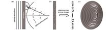
ObjectiveWith the widespread utilization of light-sensing systems and imaging systems, miniaturized and lightweight optical systems have become increasingly popular in the automotive market, industry, and medical and consumer electronics. The development of small-volume optical lenses has become crucial. Traditional optical lenses usually have large volume, low focusing efficiency, large full-width half-maximum of the spot, and poor performance in lenses with high numerical aperture (NA). The optical metasurface with sub-wavelength structures has powerful control over the light phase. Compared to traditional lenses, metalenses feature smaller volumes, thinner thickness, and better focusing performance. In the metalens design, the inverse design method has less computational complexity than the traditional design method, and meanwhile this method can provide an optimal solution for the device in a larger searchable space and improve the design efficiency. We propose an objective-first algorithm-based inverse design approach to design a low refractive index-based metalens structure. At a working wavelength of 1550 nm, the metalens has a thickness of 3.2 μm in the propagation direction, a focusing efficiency of 72%, and a high NA of 0.82. Compared with the traditional design method, this approach has low computational complexity and high efficiency. The designed devices can be rapidly manufactured by the high-precision micro-nano printing technique. Considering possible errors during the metalens fabrication, the effects of metalens contour offset and 3D rotation operations on the designed 2D metalens are further discussed.MethodsIn the objective-first algorithm, we define a simulation design area on a two-dimensional plane, and the device function can be determined by giving the incident and exit conditions on the design area. During the metalens design, we require that the device can convert the incident parallel wavefront into a spherical wavefront during exiting. After determining the phase distribution of the input and output, we iteratively update the design area by the objective-first inverse design method. This method employs the norm of Maxwell's equations as the objective function of the optimization algorithm, and the value of this objective function is called the physical residual. During the optimization iteration, we interpolate the dielectric constant, allowing it to continuously change within the design area. The advantage is that the algorithm has a larger searchable space. Meanwhile, we achieve rapid transformation between continuous and binary structures by adding a penalty function.Results and DiscussionsThe materials that make up the lens are air with a dielectric constant of 1 and a low-refractive index polymer material with a dielectric constant of 1.52. The focal length of the metalens is set to 11.3λ, the width of the device along the propagation direction is 2.1λ, and the length is 32.2λ. The grid in the design area is a square with a side length of 0.065λ, and the corresponding NA is 0.82. By utilizing the scalability of Maxwell's equations, we therefore scale the lens to a wavelength of 1550 nm. In theory, the metalens optimized by this method can be scaled as needed to meet the focusing requirements of different wavebands. At the operating wavelength of 1550 nm, the focal length of the metalens is 17.5 μm, the width is 3.2 μm, and the length is 50 μm. The grid in the design area is a square with a side length of 100 nm, and the focusing efficiency is 72%. The 3 dB bandwidth is calculated as 1447 to 1667 nm, and the half-maximum width is 0.9 μm, slightly lower than the 0.96 μm limit imposed by diffraction. Within the offset range of plus or minus 50 nm of the hyperlens profile, the focusing efficiency is above 60%. It can be concluded that the focusing performance of the lens remains essentially unchanged within the offset range of 50 nm. When the lens profile is shifted by plus or minus 100 nm, the focusing efficiency drops to around 50%, and the focusing performance of the lens starts to decline significantly. A metalens with a negative profile shift exhibits a shorter focal length, while a metalens with a positive profile shift exhibits a longer focal length.ConclusionsTo address the problems associated with traditional lenses, such as their large volume, low NA, and insufficient focusing efficiency, we focus on optimizing the structure of polymer lenses with low refractive index. This is achieved by adopting the objective-first inverse design method and the focusing characteristics of metalenses. The goal is to design a metalens structure featuring high NA and focusing efficiency, with the limitations imposed by optical diffraction performance considered. Additionally, the objective-first inverse design method is employed to relax the restrictions of Maxwell's equation and utilize it as the objective function. By breaking down the objective function into two sub-problems, the optimization process can be carried out efficiently without getting stuck in low-efficiency local solutions. Additionally, structural variables are limited to ensure that the finalized structure obtained via interpolation during the optimization is binary in nature and highly efficient. Meanwhile, we discuss the potential for contour deviation during the micro-nano printing preparation of the metalens due to manufacturing tolerances. We analyze the performance changes of the metalens within a profile deviation range of 100 nm. The results demonstrate the robustness of our optimization approach to manufacturing tolerances, with the metalens showing relatively sound focusing performance even with small deviations from the desired profile. Furthermore, we conduct three-dimensional FDTD simulations by rotating the metalens, which reveals that the metalens exhibits polarization-independent characteristics and achieves a focusing efficiency of 62% under incident conditions of circularly polarized light. ObjectiveWith the widespread utilization of light-sensing systems and imaging systems, miniaturized and lightweight optical systems have become increasingly popular in the automotive market, industry, and medical and consumer electronics. The development of small-volume optical lenses has become crucial. Traditional optical lenses usually have large volume, low focusing efficiency, large full-width half-maximum of the spot, and poor performance in lenses with high numerical aperture (NA). The optical metasurface with sub-wavelength structures has powerful control over the light phase. Compared to traditional lenses, metalenses feature smaller volumes, thinner thickness, and better focusing performance. In the metalens design, the inverse design method has less computational complexity than the traditional design method, and meanwhile this method can provide an optimal solution for the device in a larger searchable space and improve the design efficiency. We propose an objective-first algorithm-based inverse design approach to design a low refractive index-based metalens structure. At a working wavelength of 1550 nm, the metalens has a thickness of 3.2 μm in the propagation direction, a focusing efficiency of 72%, and a high NA of 0.82. Compared with the traditional design method, this approach has low computational complexity and high efficiency. The designed devices can be rapidly manufactured by the high-precision micro-nano printing technique. Considering possible errors during the metalens fabrication, the effects of metalens contour offset and 3D rotation operations on the designed 2D metalens are further discussed.MethodsIn the objective-first algorithm, we define a simulation design area on a two-dimensional plane, and the device function can be determined by giving the incident and exit conditions on the design area. During the metalens design, we require that the device can convert the incident parallel wavefront into a spherical wavefront during exiting. After determining the phase distribution of the input and output, we iteratively update the design area by the objective-first inverse design method. This method employs the norm of Maxwell's equations as the objective function of the optimization algorithm, and the value of this objective function is called the physical residual. During the optimization iteration, we interpolate the dielectric constant, allowing it to continuously change within the design area. The advantage is that the algorithm has a larger searchable space. Meanwhile, we achieve rapid transformation between continuous and binary structures by adding a penalty function.Results and DiscussionsThe materials that make up the lens are air with a dielectric constant of 1 and a low-refractive index polymer material with a dielectric constant of 1.52. The focal length of the metalens is set to 11.3λ, the width of the device along the propagation direction is 2.1λ, and the length is 32.2λ. The grid in the design area is a square with a side length of 0.065λ, and the corresponding NA is 0.82. By utilizing the scalability of Maxwell's equations, we therefore scale the lens to a wavelength of 1550 nm. In theory, the metalens optimized by this method can be scaled as needed to meet the focusing requirements of different wavebands. At the operating wavelength of 1550 nm, the focal length of the metalens is 17.5 μm, the width is 3.2 μm, and the length is 50 μm. The grid in the design area is a square with a side length of 100 nm, and the focusing efficiency is 72%. The 3 dB bandwidth is calculated as 1447 to 1667 nm, and the half-maximum width is 0.9 μm, slightly lower than the 0.96 μm limit imposed by diffraction. Within the offset range of plus or minus 50 nm of the hyperlens profile, the focusing efficiency is above 60%. It can be concluded that the focusing performance of the lens remains essentially unchanged within the offset range of 50 nm. When the lens profile is shifted by plus or minus 100 nm, the focusing efficiency drops to around 50%, and the focusing performance of the lens starts to decline significantly. A metalens with a negative profile shift exhibits a shorter focal length, while a metalens with a positive profile shift exhibits a longer focal length.ConclusionsTo address the problems associated with traditional lenses, such as their large volume, low NA, and insufficient focusing efficiency, we focus on optimizing the structure of polymer lenses with low refractive index. This is achieved by adopting the objective-first inverse design method and the focusing characteristics of metalenses. The goal is to design a metalens structure featuring high NA and focusing efficiency, with the limitations imposed by optical diffraction performance considered. Additionally, the objective-first inverse design method is employed to relax the restrictions of Maxwell's equation and utilize it as the objective function. By breaking down the objective function into two sub-problems, the optimization process can be carried out efficiently without getting stuck in low-efficiency local solutions. Additionally, structural variables are limited to ensure that the finalized structure obtained via interpolation during the optimization is binary in nature and highly efficient. Meanwhile, we discuss the potential for contour deviation during the micro-nano printing preparation of the metalens due to manufacturing tolerances. We analyze the performance changes of the metalens within a profile deviation range of 100 nm. The results demonstrate the robustness of our optimization approach to manufacturing tolerances, with the metalens showing relatively sound focusing performance even with small deviations from the desired profile. Furthermore, we conduct three-dimensional FDTD simulations by rotating the metalens, which reveals that the metalens exhibits polarization-independent characteristics and achieves a focusing efficiency of 62% under incident conditions of circularly polarized light.
Acta Optica Sinica
- Publication Date: Apr. 25, 2024
- Vol. 44, Issue 8, 0822002 (2024)

Design and Optimization of a Head-Up Display System with Variable Projection Distance
Yihan Sun, Shenjiang Wu, Bo Wang, Xiaowei Chen, and Yiming Zhang
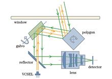
ObjectiveHead-up display (HUD) systems reduce driver visual fatigue and improve driving safety. Existing HUD only alleviates visual fatigue by reducing the times a driver looks at the dashboard. However, conventional augmented reality heads-up display (AR-HUD) system can usually only image at a fixed projection distance. When drivers approach an object, it is perceived that the image passes through the object. This causes drivers to constantly distinguish the distance between the object and the virtual image, which will lead to visual fatigue. Indeed, there is a need for a new type of HUD that makes the projection distance variable. Existing designs use an off-axis three-mirror system, by adjusting the position of the first mirror to achieve the projection distance variable. However, it will change the down angle and also need the picture generation unit (PGU) with variable angle of light output. This will increase the cost and design difficulty. It is necessary to study another way to realize the function of variable projection distance.MethodsUnlike traditional co-axial zoom optics, for HUD with variable projection distances, changing focus is not the only way. Changing the object distance and size can also realize it. We use changing magnification to realize variable projection distance and only change the position and size of the PGU. This is because, like looking in a mirror, as the object distance is larger, the virtual image is farther away. Furthermore, the distance between the PGU and the first mirror decreases at the same time as the projection distance decreases. Since none of the images of PGU emitting by the way of parallel light, as the PGU is closer to the reflector, the image reflected by the mirror is smaller. As the projection distance decreases, the tensor angle of the virtual image relative to the human eyes decreases. This design does not cause the down angle to change, and there is no need to use the PGU with a variable angle of light output. The off-axis three-mirror system generally determines the initial structure by calculating the curvature and optical spacing of the co-axial tri-reflector system. Then we adjust the off-axis angle and optimize the free-form mirror. It is complicated to obtain the different position parameters of the PGU through theoretical calculations. The theoretical data also need to be modified in combination with simulation, which will increase the workload. We design“macro”to obtain the relevant parameters directly through simulation to improve efficiency. The optimization is based on the projection distance of 10 m to optimize the free-form surface and determine the off-axis angle. The change step of the projection distance is 50 mm, and the change step of the image source size is 0.01 mm. We use random sampling to verify the function of continuously variable projection distance of the virtual image. The image quality evaluation includes transverse vertical (TV) distortion, rhombic distortion, trapezoidal distortion, grid distortion, dynamic distortion, binocular parallax, image tilt, aspect ratio distortion, MTF, spot diagrams, and field of view distortion. We evaluate the image quality in detail to better assess the imaging situation after actual manufacturing and guide suppliers to improve their products. The above information is represented in the tables and simulation diagrams.Results and DiscussionsWe use“macro”to obtain parameters related to the continuous variation of the projection distance. The image quality is analyzed when the projection distance is 10 m and 3 m respectively. The image quality is analyzed by random sampling to randomly select any projection distance within the changing range. The RMS radii of the spot diagrams in the three cases are all within the Airy spot and less than 25 μm. In addition, the grid distortion, TV distortion, rhombic distortion, and trapezoidal distortion are all less than 5%. Dynamic distortion and binocular parallax are less than 5'. The field of view distortion and aspect ratio distortion are less than 5%. Mutually using parameters of a projection distance apart 50 mm does not result in a dramatic change in image quality. In the range of the variable projection distance, the image quality meets design requirements. The designed projection distance can be continuously varied and the change step of the projection distance setting is reasonable.ConclusionsThe AR-HUD with variable projection distance can further reduce the driver's visual fatigue and improve driving safety. The means of equipment and software correction can affect the criteria for assessing image quality, but the design direction is the same. The design value of each distortion parameter should be as small as possible when conditions allow. This can give the actual manufacturing enough tolerance range. Within the space constraints of the car, we need to trade off dynamic distortion and mesh distortion. Under limited conditions, it is not possible to consider both distortions at the same time. In general, the focus should be on controlling dynamic distortion rather than mesh distortion. Appropriate distortion can be corrected by software. Compared to several design approaches, this design does not pose the risk of down angle perspective changes. The method of this design is applicable to all kinds of HUD systems based on the off-axis three-mirror system. In addition, we give the optical detection methods for reference. While our HUD architecture is relevant, the method of realizing variable projection distances is general in nature. ObjectiveHead-up display (HUD) systems reduce driver visual fatigue and improve driving safety. Existing HUD only alleviates visual fatigue by reducing the times a driver looks at the dashboard. However, conventional augmented reality heads-up display (AR-HUD) system can usually only image at a fixed projection distance. When drivers approach an object, it is perceived that the image passes through the object. This causes drivers to constantly distinguish the distance between the object and the virtual image, which will lead to visual fatigue. Indeed, there is a need for a new type of HUD that makes the projection distance variable. Existing designs use an off-axis three-mirror system, by adjusting the position of the first mirror to achieve the projection distance variable. However, it will change the down angle and also need the picture generation unit (PGU) with variable angle of light output. This will increase the cost and design difficulty. It is necessary to study another way to realize the function of variable projection distance.MethodsUnlike traditional co-axial zoom optics, for HUD with variable projection distances, changing focus is not the only way. Changing the object distance and size can also realize it. We use changing magnification to realize variable projection distance and only change the position and size of the PGU. This is because, like looking in a mirror, as the object distance is larger, the virtual image is farther away. Furthermore, the distance between the PGU and the first mirror decreases at the same time as the projection distance decreases. Since none of the images of PGU emitting by the way of parallel light, as the PGU is closer to the reflector, the image reflected by the mirror is smaller. As the projection distance decreases, the tensor angle of the virtual image relative to the human eyes decreases. This design does not cause the down angle to change, and there is no need to use the PGU with a variable angle of light output. The off-axis three-mirror system generally determines the initial structure by calculating the curvature and optical spacing of the co-axial tri-reflector system. Then we adjust the off-axis angle and optimize the free-form mirror. It is complicated to obtain the different position parameters of the PGU through theoretical calculations. The theoretical data also need to be modified in combination with simulation, which will increase the workload. We design“macro”to obtain the relevant parameters directly through simulation to improve efficiency. The optimization is based on the projection distance of 10 m to optimize the free-form surface and determine the off-axis angle. The change step of the projection distance is 50 mm, and the change step of the image source size is 0.01 mm. We use random sampling to verify the function of continuously variable projection distance of the virtual image. The image quality evaluation includes transverse vertical (TV) distortion, rhombic distortion, trapezoidal distortion, grid distortion, dynamic distortion, binocular parallax, image tilt, aspect ratio distortion, MTF, spot diagrams, and field of view distortion. We evaluate the image quality in detail to better assess the imaging situation after actual manufacturing and guide suppliers to improve their products. The above information is represented in the tables and simulation diagrams.Results and DiscussionsWe use“macro”to obtain parameters related to the continuous variation of the projection distance. The image quality is analyzed when the projection distance is 10 m and 3 m respectively. The image quality is analyzed by random sampling to randomly select any projection distance within the changing range. The RMS radii of the spot diagrams in the three cases are all within the Airy spot and less than 25 μm. In addition, the grid distortion, TV distortion, rhombic distortion, and trapezoidal distortion are all less than 5%. Dynamic distortion and binocular parallax are less than 5'. The field of view distortion and aspect ratio distortion are less than 5%. Mutually using parameters of a projection distance apart 50 mm does not result in a dramatic change in image quality. In the range of the variable projection distance, the image quality meets design requirements. The designed projection distance can be continuously varied and the change step of the projection distance setting is reasonable.ConclusionsThe AR-HUD with variable projection distance can further reduce the driver's visual fatigue and improve driving safety. The means of equipment and software correction can affect the criteria for assessing image quality, but the design direction is the same. The design value of each distortion parameter should be as small as possible when conditions allow. This can give the actual manufacturing enough tolerance range. Within the space constraints of the car, we need to trade off dynamic distortion and mesh distortion. Under limited conditions, it is not possible to consider both distortions at the same time. In general, the focus should be on controlling dynamic distortion rather than mesh distortion. Appropriate distortion can be corrected by software. Compared to several design approaches, this design does not pose the risk of down angle perspective changes. The method of this design is applicable to all kinds of HUD systems based on the off-axis three-mirror system. In addition, we give the optical detection methods for reference. While our HUD architecture is relevant, the method of realizing variable projection distances is general in nature.
Acta Optica Sinica
- Publication Date: Apr. 25, 2024
- Vol. 44, Issue 8, 0822001 (2024)
Selection Method of Risley Prisms Scanning Trajectory Based on Velocity Ratio
Linsen Duan, Hongbo Xie, Jun Ma, and Lei Yang
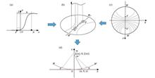
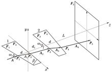
ObjectiveThe Risley prism scanning system is a useful supplement to traditional rotating frame and mirror scanning systems. It features a compact structure, low optical loss, excellent dynamic performance, and a large scanning field of view, and has broad application prospects in lidars, laser communication, and laser guidance. In the practical applications of this system, it is important to select the scanning trajectory reasonably, which will directly affect the scanning efficiency of the system and the acquisition probability of the target. When the parameters and relative positions of the Risley prism are determined, the rotation velocity ratio of the Risley prism is variable and controllable to obtain the scanning trajectories of different shapes. We aim to study the relationship between the velocity ratio with the number of scanning points and petals, then summarize the internal rules of the velocity ratio and scanning trajectory, and evaluate the scanning time and coverage rate of the scanning trajectory under different velocity ratios. Therefore, our study has a guiding significance for selecting the scanning trajectory that meets the scanning efficiency requirements.MethodsFirstly, the forward problem of the Risley prism is solved by the non-axial ray tracing algorithm, and the scanning trajectories under different velocity ratios can be obtained. Secondly, the number of scanning points is calculated according to the rotation velocity of the Risley prism and sampling interval, and the number of scanning petals is calculated according to the number of minimum points of the distance curve between scanning points and coordinate origin. Then, the velocity ratio is classified according to its absolute value and fractional part, and the formula for calculating the number of scanning petals by the velocity ratio is established. The scanning trajectory rules of the 2-element Risley prism are analyzed, and the scanning time and coverage rate under different velocity ratios are evaluated. Finally, the scanning trajectory of the 3-element Risley prism is regarded as the superposition and cancellation of the scanning trajectory of the 2-element Risley prism, and the scanning time and coverage rate can be evaluated according to the scanning trajectory rules of the 2-element Risley prism. Additionally, the condition for the 3-element Risley prism to obtain a regular symmetry scanning trajectory without a large scanning blind zone is proposed by analyzing the velocity ratio.Results and DiscussionsThe scanning trajectory of 2-element Risley prism has the following rules (Table 1 and Fig. 4). When M is positive, the scanning trajectory is inner petal, and the trajectory is outer petal under negative M. When M is an integer, the scanning time under different velocity ratios is the same, and when M is a decimal, the scanning time under each type of velocity ratio is the same if the number of decimal places is the same. Under the different numbers of decimal places, the larger number of decimal places leads to longer scanning time. Therefore, the number of decimal places should not be too large. For each type of velocity ratio, when M is of the same sign, the larger |M| brings a larger coverage rate. The scanning trajectory of 3-element Risley prism has the following rules (Table 4 and Fig. 10): only when the scanning petals of 2-element Risley prism are doubled (1-2 times) with the velocity ratio of M1 and M2, and the scanning points are also doubled (1-2 times), the scanning trajectory of 3-element Risley prism is regular symmetry and has no large scanning blind zone. When M1 and M2 are both positive, the scanning trajectory is inner petal. When M1 and M2 are both negative or different signs, the scanning trajectory is the outer petal. Additionally, the scanning time and coverage rate of the 3-element Risley prism can be evaluated according to the scanning trajectory rules of the 2-element Risley prism.ConclusionsAs the scanning trajectory of the Risley prism determines the scanning efficiency of the system and the acquisition probability of the target, it is important to study the method of selecting the scanning trajectory by analyzing the velocity ratio. Based on the non-axial ray tracing algorithm, the forward problem of the Risley prism scanning system is solved. Then the petal-shaped scanning trajectories under different velocity ratios are obtained, and the number of scanning points and scanning petals are calculated, which is then adopted to summarize the rules between the scanning trajectory and velocity ratio. The scanning time and coverage rate of the scanning trajectory under different velocity ratios are evaluated. Meanwhile, the condition for the 3-element Risley prism to obtain a regular symmetry scanning trajectory without a large scanning blind zone is proposed. The obtained rules and conclusions can be employed to reasonably determine the velocity ratio in the practical applications of the Risley prism scanning system to select the scanning trajectory that meets the scanning efficiency requirements. However, the scanning trajectory of the Risley prism is sensitive to the velocity ratio, and there will be deviations between the actual and set velocity ratios in the rotation control. Therefore, the influence of such deviations on the scanning trajectory can be further explored. ObjectiveThe Risley prism scanning system is a useful supplement to traditional rotating frame and mirror scanning systems. It features a compact structure, low optical loss, excellent dynamic performance, and a large scanning field of view, and has broad application prospects in lidars, laser communication, and laser guidance. In the practical applications of this system, it is important to select the scanning trajectory reasonably, which will directly affect the scanning efficiency of the system and the acquisition probability of the target. When the parameters and relative positions of the Risley prism are determined, the rotation velocity ratio of the Risley prism is variable and controllable to obtain the scanning trajectories of different shapes. We aim to study the relationship between the velocity ratio with the number of scanning points and petals, then summarize the internal rules of the velocity ratio and scanning trajectory, and evaluate the scanning time and coverage rate of the scanning trajectory under different velocity ratios. Therefore, our study has a guiding significance for selecting the scanning trajectory that meets the scanning efficiency requirements.MethodsFirstly, the forward problem of the Risley prism is solved by the non-axial ray tracing algorithm, and the scanning trajectories under different velocity ratios can be obtained. Secondly, the number of scanning points is calculated according to the rotation velocity of the Risley prism and sampling interval, and the number of scanning petals is calculated according to the number of minimum points of the distance curve between scanning points and coordinate origin. Then, the velocity ratio is classified according to its absolute value and fractional part, and the formula for calculating the number of scanning petals by the velocity ratio is established. The scanning trajectory rules of the 2-element Risley prism are analyzed, and the scanning time and coverage rate under different velocity ratios are evaluated. Finally, the scanning trajectory of the 3-element Risley prism is regarded as the superposition and cancellation of the scanning trajectory of the 2-element Risley prism, and the scanning time and coverage rate can be evaluated according to the scanning trajectory rules of the 2-element Risley prism. Additionally, the condition for the 3-element Risley prism to obtain a regular symmetry scanning trajectory without a large scanning blind zone is proposed by analyzing the velocity ratio.Results and DiscussionsThe scanning trajectory of 2-element Risley prism has the following rules (Table 1 and Fig. 4). When M is positive, the scanning trajectory is inner petal, and the trajectory is outer petal under negative M. When M is an integer, the scanning time under different velocity ratios is the same, and when M is a decimal, the scanning time under each type of velocity ratio is the same if the number of decimal places is the same. Under the different numbers of decimal places, the larger number of decimal places leads to longer scanning time. Therefore, the number of decimal places should not be too large. For each type of velocity ratio, when M is of the same sign, the larger |M| brings a larger coverage rate. The scanning trajectory of 3-element Risley prism has the following rules (Table 4 and Fig. 10): only when the scanning petals of 2-element Risley prism are doubled (1-2 times) with the velocity ratio of M1 and M2, and the scanning points are also doubled (1-2 times), the scanning trajectory of 3-element Risley prism is regular symmetry and has no large scanning blind zone. When M1 and M2 are both positive, the scanning trajectory is inner petal. When M1 and M2 are both negative or different signs, the scanning trajectory is the outer petal. Additionally, the scanning time and coverage rate of the 3-element Risley prism can be evaluated according to the scanning trajectory rules of the 2-element Risley prism.ConclusionsAs the scanning trajectory of the Risley prism determines the scanning efficiency of the system and the acquisition probability of the target, it is important to study the method of selecting the scanning trajectory by analyzing the velocity ratio. Based on the non-axial ray tracing algorithm, the forward problem of the Risley prism scanning system is solved. Then the petal-shaped scanning trajectories under different velocity ratios are obtained, and the number of scanning points and scanning petals are calculated, which is then adopted to summarize the rules between the scanning trajectory and velocity ratio. The scanning time and coverage rate of the scanning trajectory under different velocity ratios are evaluated. Meanwhile, the condition for the 3-element Risley prism to obtain a regular symmetry scanning trajectory without a large scanning blind zone is proposed. The obtained rules and conclusions can be employed to reasonably determine the velocity ratio in the practical applications of the Risley prism scanning system to select the scanning trajectory that meets the scanning efficiency requirements. However, the scanning trajectory of the Risley prism is sensitive to the velocity ratio, and there will be deviations between the actual and set velocity ratios in the rotation control. Therefore, the influence of such deviations on the scanning trajectory can be further explored.
Acta Optica Sinica
- Publication Date: Apr. 10, 2024
- Vol. 44, Issue 7, 0722003 (2024)

Athermalization Design of Uncooled Long Waveband Infrared Continuous Zoom Optical System
Yufeng Tang, Shan Mao, Yichen Song, Tao Lai, Peiqi Yuan, Xiaowei Ding, and Jianlin Zhao
ObjectiveCompared with the traditional visible light imaging technology, infrared spectral thermal imaging technology utilizes the thermal radiation emitted by objects to obtain images of target objects, with unique advantages in target detection and tracking. Particularly in the long-wave infrared (LWIR) bands, it demonstrates superior transmittance, increased propagation distance, and enhanced detection performance. Consequently, infrared cameras possess application significance in the high-end commerce, monitoring, and other fields. However, conventional thermal imaging cameras are limited by a fixed focal length, which enables observation only within a specific field of view or area and hampers search and observation capabilities. To this end, the infrared zoom thermal imaging camera is developed. By continuously adjusting the field of view and magnification relationship via a continuous zoom optical system, seamless range size adjustment is achieved, with stability and image clarity maintained. However, the majority of existing LWIR zoom systems incorporate diffractive surfaces, which results in complex design requirements, elevated processing and assembly demands, and increased system costs. Furthermore, the design of certain LWIR zoom systems overlooks the influence of ambient temperature on image quality, subsequently compromising practicality. Thus, it is imperative to devise a low-cost, compact, and uncooled long-wave infrared continuous zoom optical system that preserves excellent image quality across a wide range of temperature variations and exhibits strong practicality. We aim to make the design outcomes contribute to advancements in military weapon targeting, handheld thermal imaging cameras, unmanned vehicles, and related fields.MethodsTo meet the requirements of the specific application environment, we have determined the appropriate initial structure for the design. The mechanical positive group compensation method is chosen as the compensation technique for the system. Additionally, the introduction of sulfur glass helps control chromatic aberration and minimize thermal defocus within the system. Meanwhile, the temperature compensation group employs the smallest aperture lens in the system to address temperature variations and maintain image quality. We incorporate the electro-mechanical active non-thermalization method, allowing the temperature compensation mirror group to be adjusted and ensuring excellent imaging quality across a wide temperature range. Additionally, we utilize Zemax OpticStudio software to optimize the design to help control the system size and improve overall image quality. By adopting this iterative process, we design a non-thermalized continuous zoom optical system for LWIR. The designed system takes into account the practicality of implementation, cost-effectiveness, and compactness while delivering excellent image quality and addressing thermal variations. This design has significant potential for applications in handheld thermal imaging cameras, unmanned vehicles, and other related areas.Results and DiscussionsAfter implementing the Zemax OpticStudio software for optimization, a continuous zoom optical system for LWIR consisting of seven lenses is designed. The materials chosen for the lenses are ZnSe and ZnS for the first and second lenses, IRG24 for the fourth lens, and Ge for the third and fifth to seventh lenses (Table 2). In this optical system, five even-ordered aspherical surfaces are employed, and their feasibility for machining is analyzed (Table 3 and Fig. 6), with the remaining surfaces being standard spherical surfaces. The evaluation of the system's imaging quality produces the following results. The modulation transfer function (MTF) exceeds 0.32 at all focal lengths, which is close to the diffraction limit (Fig. 3). The aberration values are also found to be less than 1.8% at the short focus and 0.4% at the intermediate and long focuses (Fig. 4). Furthermore, the energy of the field-of-view envelope is more than 82% at the short focus, 70% at the intermediate focus, and 77% at the long focus for a pixel size of 25 μm×25 μm. At short focal length, it exceeds 70% and is greater than 77% at the long focal length (Fig. 5). The out-of-focus amount of the image plane of the optical system at different temperatures is within the depth of focus of the system (Table 4). Additionally, tolerance analysis demonstrates that the system is easily machinable and has a high degree of realizability (Tables 5 and 6). Meanwhile, the cam curve of the lens displays a smooth trend without any inflection point (Fig. 7).ConclusionsFor the LWIR 320 pixel×320 pixel infrared detector, a continuous zoomable non-thermalized uncooled LWIR optical system is designed by mechanical positive group compensation and electromechanical active compensation. The system achieves MTF values close to the diffraction limit at all focal lengths, indicating excellent image sharpness. It has a compact structure, minimal aberrations, long working distance, and high overall imaging quality. The design strategy focuses on cost reduction by incorporating only aspherical surfaces while maintaining system performance. This approach helps minimize the system's size and weight, simplifies its complexity, and ensures smooth motion curves for both the zoom and compensation groups. The cam mechanism chosen for this design is relatively straightforward to process. Given these features and advantages, the system holds application significance in various fields such as searching, tracking, and detecting, and can be effectively utilized in scenarios where high-quality infrared imaging is crucial. ObjectiveCompared with the traditional visible light imaging technology, infrared spectral thermal imaging technology utilizes the thermal radiation emitted by objects to obtain images of target objects, with unique advantages in target detection and tracking. Particularly in the long-wave infrared (LWIR) bands, it demonstrates superior transmittance, increased propagation distance, and enhanced detection performance. Consequently, infrared cameras possess application significance in the high-end commerce, monitoring, and other fields. However, conventional thermal imaging cameras are limited by a fixed focal length, which enables observation only within a specific field of view or area and hampers search and observation capabilities. To this end, the infrared zoom thermal imaging camera is developed. By continuously adjusting the field of view and magnification relationship via a continuous zoom optical system, seamless range size adjustment is achieved, with stability and image clarity maintained. However, the majority of existing LWIR zoom systems incorporate diffractive surfaces, which results in complex design requirements, elevated processing and assembly demands, and increased system costs. Furthermore, the design of certain LWIR zoom systems overlooks the influence of ambient temperature on image quality, subsequently compromising practicality. Thus, it is imperative to devise a low-cost, compact, and uncooled long-wave infrared continuous zoom optical system that preserves excellent image quality across a wide range of temperature variations and exhibits strong practicality. We aim to make the design outcomes contribute to advancements in military weapon targeting, handheld thermal imaging cameras, unmanned vehicles, and related fields.MethodsTo meet the requirements of the specific application environment, we have determined the appropriate initial structure for the design. The mechanical positive group compensation method is chosen as the compensation technique for the system. Additionally, the introduction of sulfur glass helps control chromatic aberration and minimize thermal defocus within the system. Meanwhile, the temperature compensation group employs the smallest aperture lens in the system to address temperature variations and maintain image quality. We incorporate the electro-mechanical active non-thermalization method, allowing the temperature compensation mirror group to be adjusted and ensuring excellent imaging quality across a wide temperature range. Additionally, we utilize Zemax OpticStudio software to optimize the design to help control the system size and improve overall image quality. By adopting this iterative process, we design a non-thermalized continuous zoom optical system for LWIR. The designed system takes into account the practicality of implementation, cost-effectiveness, and compactness while delivering excellent image quality and addressing thermal variations. This design has significant potential for applications in handheld thermal imaging cameras, unmanned vehicles, and other related areas.Results and DiscussionsAfter implementing the Zemax OpticStudio software for optimization, a continuous zoom optical system for LWIR consisting of seven lenses is designed. The materials chosen for the lenses are ZnSe and ZnS for the first and second lenses, IRG24 for the fourth lens, and Ge for the third and fifth to seventh lenses (Table 2). In this optical system, five even-ordered aspherical surfaces are employed, and their feasibility for machining is analyzed (Table 3 and Fig. 6), with the remaining surfaces being standard spherical surfaces. The evaluation of the system's imaging quality produces the following results. The modulation transfer function (MTF) exceeds 0.32 at all focal lengths, which is close to the diffraction limit (Fig. 3). The aberration values are also found to be less than 1.8% at the short focus and 0.4% at the intermediate and long focuses (Fig. 4). Furthermore, the energy of the field-of-view envelope is more than 82% at the short focus, 70% at the intermediate focus, and 77% at the long focus for a pixel size of 25 μm×25 μm. At short focal length, it exceeds 70% and is greater than 77% at the long focal length (Fig. 5). The out-of-focus amount of the image plane of the optical system at different temperatures is within the depth of focus of the system (Table 4). Additionally, tolerance analysis demonstrates that the system is easily machinable and has a high degree of realizability (Tables 5 and 6). Meanwhile, the cam curve of the lens displays a smooth trend without any inflection point (Fig. 7).ConclusionsFor the LWIR 320 pixel×320 pixel infrared detector, a continuous zoomable non-thermalized uncooled LWIR optical system is designed by mechanical positive group compensation and electromechanical active compensation. The system achieves MTF values close to the diffraction limit at all focal lengths, indicating excellent image sharpness. It has a compact structure, minimal aberrations, long working distance, and high overall imaging quality. The design strategy focuses on cost reduction by incorporating only aspherical surfaces while maintaining system performance. This approach helps minimize the system's size and weight, simplifies its complexity, and ensures smooth motion curves for both the zoom and compensation groups. The cam mechanism chosen for this design is relatively straightforward to process. Given these features and advantages, the system holds application significance in various fields such as searching, tracking, and detecting, and can be effectively utilized in scenarios where high-quality infrared imaging is crucial.
Acta Optica Sinica
- Publication Date: Apr. 10, 2024
- Vol. 44, Issue 7, 0722002 (2024)
Opto-Mechanical Thermal Integration Analysis and Optimization of KrF Deep Ultraviolet Lithography Projection Lens
Xing Han, Lun Jiang, Yanwei Li, and Junchi Li
ObjectiveTo achieve the design of high-precision deep ultraviolet lithography projection lenses, we propose a method for opto-mechanical thermal integration analysis and optimization of deep ultraviolet lithography projection lenses. This method can analyze the influence of factors such as gravity, mechanical support structure, and temperature variations on the image quality of the optical system during the design phase. A novel support mechanism combining axial multi-point and circumferential three-point adhesive supports is designed to meet the requirements of ultra-high-precision positioning of the optical elements. Meanwhile, sensitivity analysis is conducted on individual optical elements using the sensitivity analysis method to optimize the image quality in opto-mechanical thermal integration analysis conditions, which provides insights and directions for improving the image quality of the optical system.MethodsInitially, an innovative support mechanism combining axial multi-point and circumferential three-point adhesive supports is employed to achieve ultra-high precision positioning requirements for a 212.51 mm aperture optical element. Subsequently, the thermal-mechanical coupling analysis of the novel support structure is conducted using the finite element analysis method. The obtained results are adopted in a developed Fringe Zernike polynomial fitting program to compute the surface peak valley (PV) and root mean square (RMS) of the optical element and thus validate the rationality of the opto-mechanical structure. Furthermore, the SigFit software serves as the opto-mechanical interface software, enabling the analysis of individual optical element sensitivity and the influence of overall optical element surface deformations on the wavefront aberration RMS value and calibration of F-tan θ distortion within the opto-mechanical thermal integration analysis framework. Finally, localized optimization is performed on elements with high sensitivity to reduce their sensitivity and ultimately optimize the image quality of the entire optical system.ConclusionsIn thermal-mechanical coupling conditions (reference temperature of 22.5 ℃, ±2.5 ℃, gravitational force), the maximum surface profile RMS value of the optical elements is verified to be ≤9.86 nm, which satisfies the stringent ultra-high precision positioning requirements. In opto-mechanical thermal integration analysis conditions (reference temperature of 22.5 ℃, ±2 ℃ limit operating temperature, gravitational force), the optimized wavefront aberration RMS value of the optical system is determined to be 10.50 nm, with a corresponding F-tan θ distortion calibration of 6.00 nm. Compared to pre-optimization results, the wavefront aberration RMS demonstrates a remarkable improvement of 46.98%, while the corresponding F-tan θ distortion shows an impressive enhancement of 77.69%, successfully meeting the design specifications. ObjectiveTo achieve the design of high-precision deep ultraviolet lithography projection lenses, we propose a method for opto-mechanical thermal integration analysis and optimization of deep ultraviolet lithography projection lenses. This method can analyze the influence of factors such as gravity, mechanical support structure, and temperature variations on the image quality of the optical system during the design phase. A novel support mechanism combining axial multi-point and circumferential three-point adhesive supports is designed to meet the requirements of ultra-high-precision positioning of the optical elements. Meanwhile, sensitivity analysis is conducted on individual optical elements using the sensitivity analysis method to optimize the image quality in opto-mechanical thermal integration analysis conditions, which provides insights and directions for improving the image quality of the optical system.MethodsInitially, an innovative support mechanism combining axial multi-point and circumferential three-point adhesive supports is employed to achieve ultra-high precision positioning requirements for a 212.51 mm aperture optical element. Subsequently, the thermal-mechanical coupling analysis of the novel support structure is conducted using the finite element analysis method. The obtained results are adopted in a developed Fringe Zernike polynomial fitting program to compute the surface peak valley (PV) and root mean square (RMS) of the optical element and thus validate the rationality of the opto-mechanical structure. Furthermore, the SigFit software serves as the opto-mechanical interface software, enabling the analysis of individual optical element sensitivity and the influence of overall optical element surface deformations on the wavefront aberration RMS value and calibration of F-tan θ distortion within the opto-mechanical thermal integration analysis framework. Finally, localized optimization is performed on elements with high sensitivity to reduce their sensitivity and ultimately optimize the image quality of the entire optical system.ConclusionsIn thermal-mechanical coupling conditions (reference temperature of 22.5 ℃, ±2.5 ℃, gravitational force), the maximum surface profile RMS value of the optical elements is verified to be ≤9.86 nm, which satisfies the stringent ultra-high precision positioning requirements. In opto-mechanical thermal integration analysis conditions (reference temperature of 22.5 ℃, ±2 ℃ limit operating temperature, gravitational force), the optimized wavefront aberration RMS value of the optical system is determined to be 10.50 nm, with a corresponding F-tan θ distortion calibration of 6.00 nm. Compared to pre-optimization results, the wavefront aberration RMS demonstrates a remarkable improvement of 46.98%, while the corresponding F-tan θ distortion shows an impressive enhancement of 77.69%, successfully meeting the design specifications.
Acta Optica Sinica
- Publication Date: Apr. 10, 2024
- Vol. 44, Issue 7, 0722001 (2024)
System Design of Space Solar Extreme Ultraviolet Three-Waveband Imaging Spectrometer
Ziwen Duan, Yangguang Xing, Jilong Peng, Shuwu Dai, Ying Wang, Chenglin Zhu, Lei Yan, Yifan Huang, Yue Liu, and Lin Li
ObjectiveThe solar upper atmosphere including the corona, transition region, and chromosphere is composed of hot and highly dynamic magnetized plasma, from which highly ionized ions emit abundant extreme ultraviolet (EUV) spectral lines. Existing EUV imaging spectrometers can only conduct imaging on one or two target regions of the solar upper atmosphere but cannot diagnose the whole region in a wide spectral and spatial scale using a single instrument. This severely restricts our understanding of the energy and material transport processes in solar eruptive activities. Therefore, we propose and design a solar EUV three-waveband imaging spectrometer with an elliptical varied line-space (EVLS) grating that operates at non-Rowland circle mounting. This innovative solar EUV imaging spectrometer boasts exceptional spectral imaging performance in an extremely large off-axis slit field of view (FOV) while maintaining a compact instrument package. Furthermore, it provides excellent grating aberration correction even at very high spectrograph magnifications and beam speeds. We hope that our spectral imaging strategy and instrument system design will be instrumental in the simultaneous observation of the solar corona, transition region, and chromosphere in the near future.MethodsThe instrument utilizes an EVLS grating as the diffraction spectroscopic element. To achieve simultaneous correction of aberrations and free-astigmatism in all three spectral bands, we analyze the grating for aberrations by employing the optical path function and Fermat's principle. The correction condition of off-axis aberrations for the grating is obtained by optimizing the elliptical base shape parameters, line-space parameters, and structure parameters of the EVLS grating, with the grating's spectral focusing formula and spatial focusing curve formula considered. The global optimal solution for the instrument is then obtained via the simulated annealing algorithm and computer-aided design method to build the optimal model of the solar EUV three-waveband imaging spectrometer. Finally, the Monte Carlo method is adopted to non-sequentially trace different spectral line pairs in the target spectral band to verify the spectral imaging performance of the designed system.Results and DiscussionsFigure 3 shows the final optimized optical system layout of the designed solar EUV three-waveband imaging spectrometer. The working wavelengths of 17-21 nm, 70-80 nm, and 95-105 nm are respectively utilized for observing the solar corona, transition region, and chromosphere. The detector for the 17-21 nm band adopts the charge-coupled device (CCD) structure of e2v technology with a pixel size of 13.5 μm, while the detectors for the 70-80 nm and 95-105 nm bands leverage an active pixel sensor (APS) structure with micro-channel plate (MCP) technology, and the pixel size is 20 μm. The entire instrument has an optical envelope volume of 1700 mm×370 mm×100 mm, and the slit has five different widths to adapt to different spatial and temporal scales of solar eruption activities. High-resolution spectral imaging of the two-dimensional solar disk with an FOV of 9.6′×5.0′ can be achieved by stepwise rotation of the off-axis primary mirror.The instrument exhibits excellent imaging performance. The root mean square (RMS) radii at 17-21 nm are all less than 6 μm, while the RMS radii at 70-80 nm and 95-105 nm are mostly less than 10 μm. As the FOV increases, the radius of the diffractive spot RMS changes smoothly [Figs. 5(d)-5(f)], which indicates good correction of off-axis aberrations. At 19 nm, the modulation transfer function values at the Nyquist spatial frequency (37 lp/mm) are all greater than 0.6 [Fig. 6(a)], and the geometric encircled energy within a single pixel size (13.5 μm) is better than 82.5% [Fig. 7 (a)]. At 75 nm and 100 nm, the modulation transfer function values at the Nyquist spatial frequency (25 lp/mm) are both greater than 0.4 [Figs. 6(b)-6(c)], and the geometric encircled energy within a single pixel size is 80.5% and 85.9% [Figs. 7(b)-7(c)] for each. Generally, the spatial resolution of the system is better than 0.6″. The simulation results of non-sequential ray tracing show that the slit image length is 19.67 mm, which is consistent with the theoretically calculated value of 19.60 mm [Fig. 8 (b)]. The slit images of the spectral lines with their respective calculated ideal spectral resolution intervals at the three center wavelengths of 19, 75, and 100 nm are separated [Fig. 8 (a)]. Therefore, the spectral resolution of the imaging spectrometer system is better than 0.006 nm in the 17-21 nm band and better than 0.008 nm in the 70-80 nm and 95-105 nm bands.ConclusionsWe propose an innovative slit-scanning spectral imaging architecture that operates at 17-21 nm, 70-80 nm, and 95-105 nm. It can simultaneously diagnose and observe important plasma spectral lines in the solar corona, transition region, and chromosphere. Meanwhile, the theory of correcting the image aberrations caused by EVLS grating operating at non-Rowland circle mounting is studied. This structure can correct off-axis grating aberrations in a relatively compact design to achieve high-resolution spectroscopic imaging with broadband and large off-axis FOV. The ray tracing simulation experimental results reveal that the system's spatial resolution is better than 0.6″, and its spectral resolution is better than 0.006 nm at 17-21 nm, and better than 0.008 nm at 70-80 nm and 95-105 nm respectively. The advanced design research of this instrument has theoretical significance for the development and research of China's solar EUV imaging spectrometers in the near future and provides references for the model selection of China's future solar space exploration missions. ObjectiveThe solar upper atmosphere including the corona, transition region, and chromosphere is composed of hot and highly dynamic magnetized plasma, from which highly ionized ions emit abundant extreme ultraviolet (EUV) spectral lines. Existing EUV imaging spectrometers can only conduct imaging on one or two target regions of the solar upper atmosphere but cannot diagnose the whole region in a wide spectral and spatial scale using a single instrument. This severely restricts our understanding of the energy and material transport processes in solar eruptive activities. Therefore, we propose and design a solar EUV three-waveband imaging spectrometer with an elliptical varied line-space (EVLS) grating that operates at non-Rowland circle mounting. This innovative solar EUV imaging spectrometer boasts exceptional spectral imaging performance in an extremely large off-axis slit field of view (FOV) while maintaining a compact instrument package. Furthermore, it provides excellent grating aberration correction even at very high spectrograph magnifications and beam speeds. We hope that our spectral imaging strategy and instrument system design will be instrumental in the simultaneous observation of the solar corona, transition region, and chromosphere in the near future.MethodsThe instrument utilizes an EVLS grating as the diffraction spectroscopic element. To achieve simultaneous correction of aberrations and free-astigmatism in all three spectral bands, we analyze the grating for aberrations by employing the optical path function and Fermat's principle. The correction condition of off-axis aberrations for the grating is obtained by optimizing the elliptical base shape parameters, line-space parameters, and structure parameters of the EVLS grating, with the grating's spectral focusing formula and spatial focusing curve formula considered. The global optimal solution for the instrument is then obtained via the simulated annealing algorithm and computer-aided design method to build the optimal model of the solar EUV three-waveband imaging spectrometer. Finally, the Monte Carlo method is adopted to non-sequentially trace different spectral line pairs in the target spectral band to verify the spectral imaging performance of the designed system.Results and DiscussionsFigure 3 shows the final optimized optical system layout of the designed solar EUV three-waveband imaging spectrometer. The working wavelengths of 17-21 nm, 70-80 nm, and 95-105 nm are respectively utilized for observing the solar corona, transition region, and chromosphere. The detector for the 17-21 nm band adopts the charge-coupled device (CCD) structure of e2v technology with a pixel size of 13.5 μm, while the detectors for the 70-80 nm and 95-105 nm bands leverage an active pixel sensor (APS) structure with micro-channel plate (MCP) technology, and the pixel size is 20 μm. The entire instrument has an optical envelope volume of 1700 mm×370 mm×100 mm, and the slit has five different widths to adapt to different spatial and temporal scales of solar eruption activities. High-resolution spectral imaging of the two-dimensional solar disk with an FOV of 9.6′×5.0′ can be achieved by stepwise rotation of the off-axis primary mirror.The instrument exhibits excellent imaging performance. The root mean square (RMS) radii at 17-21 nm are all less than 6 μm, while the RMS radii at 70-80 nm and 95-105 nm are mostly less than 10 μm. As the FOV increases, the radius of the diffractive spot RMS changes smoothly [Figs. 5(d)-5(f)], which indicates good correction of off-axis aberrations. At 19 nm, the modulation transfer function values at the Nyquist spatial frequency (37 lp/mm) are all greater than 0.6 [Fig. 6(a)], and the geometric encircled energy within a single pixel size (13.5 μm) is better than 82.5% [Fig. 7 (a)]. At 75 nm and 100 nm, the modulation transfer function values at the Nyquist spatial frequency (25 lp/mm) are both greater than 0.4 [Figs. 6(b)-6(c)], and the geometric encircled energy within a single pixel size is 80.5% and 85.9% [Figs. 7(b)-7(c)] for each. Generally, the spatial resolution of the system is better than 0.6″. The simulation results of non-sequential ray tracing show that the slit image length is 19.67 mm, which is consistent with the theoretically calculated value of 19.60 mm [Fig. 8 (b)]. The slit images of the spectral lines with their respective calculated ideal spectral resolution intervals at the three center wavelengths of 19, 75, and 100 nm are separated [Fig. 8 (a)]. Therefore, the spectral resolution of the imaging spectrometer system is better than 0.006 nm in the 17-21 nm band and better than 0.008 nm in the 70-80 nm and 95-105 nm bands.ConclusionsWe propose an innovative slit-scanning spectral imaging architecture that operates at 17-21 nm, 70-80 nm, and 95-105 nm. It can simultaneously diagnose and observe important plasma spectral lines in the solar corona, transition region, and chromosphere. Meanwhile, the theory of correcting the image aberrations caused by EVLS grating operating at non-Rowland circle mounting is studied. This structure can correct off-axis grating aberrations in a relatively compact design to achieve high-resolution spectroscopic imaging with broadband and large off-axis FOV. The ray tracing simulation experimental results reveal that the system's spatial resolution is better than 0.6″, and its spectral resolution is better than 0.006 nm at 17-21 nm, and better than 0.008 nm at 70-80 nm and 95-105 nm respectively. The advanced design research of this instrument has theoretical significance for the development and research of China's solar EUV imaging spectrometers in the near future and provides references for the model selection of China's future solar space exploration missions.
Acta Optica Sinica
- Publication Date: Mar. 10, 2024
- Vol. 44, Issue 6, 0622001 (2024)
On-Chip Photonic Lead Direct Writing Technology Based on Nano-Alignment Guide Star
Bowen Sun, Guozun Zhou, Zhenyu Yang, Yinxu Bian, Cuifang Kuang, and Xu Liu
ObjectiveIntegrated photonic chip is a key technology that combines laser light sources, modulators, waveguides, detectors, and other photonic devices into a compact, high-bandwidth, low-latency, and energy-efficient package. They hold significant importance in fields such as quantum information processing and optical communication and play a crucial role in the next generation of communication systems and data interconnectivity. The two-photon polymerization technology for three-dimensional micro and nanofabrication has pushed the resolution of laser direct writing (LDW) beyond the limit imposed by optical diffraction to achieve sub-hundred nanometer scales. Meanwhile, it has significant advantages such as simple processing workflow, minimal thermal effect, and low optical threshold damage, which makes it suitable for high-precision, high-density on-chip interconnections. Additionally, the exceptional flexibility of two-photon laser direct writing systems allows for effective adaptation to the varying spatial positions, dimensions, and orientations of interfaces in on-chip interconnections, substantially reducing the requirements for active alignment. In contrast to projection lithography which processes planar structures at one time, on-chip photonic interconnections demand high-precision positioning for the three-dimensional photonic lead at the tips of the waveguides. The writing position accuracy directly influences the signal coupling quality, emphasizing the need for high-precision alignment solutions.MethodsWe focus on the research on nanoscale alignment techniques in high-precision laser direct writing for on-chip photonic waveguides. In the context of a two-photon three-dimensional direct writing system (Fig. 1), machine vision and image processing technologies based on guide star nano-alignment are employed. Intelligent recognition and positioning of nano-alignment markers are carried out in Figs. 5 and 6 to enable the definition of the processing area and the establishment of a three-dimensional processing coordinate system. The two-photon laser writing beam is then precisely controlled, aided by a differential confocal system for axial spatial positioning. This approach facilitates the high-precision and high-density 3D direct writing of on-chip photonic lead interconnections within nanoscale structures between waveguides. By enabling intelligent recognition and alignment of specific markers or distinctive graphical features within the direct writing lithography system, the system is equipped with practical functions, including the fabrication of various complex structures. This has significant scientific and practical implications in high-precision processing areas such as chip packaging, multi-material functional structure fabrication, and complex structure modifications.Results and DiscussionsDue to limitations imposed by the field of view, the two-photon laser direct writing system cannot write photonic leads of approximately 270 μm in length at one time. Consequently, each one is divided into three segments and written separately. Fig. 7(a) displays the result of a single writing operation, and Fig. 7(b) illustrates the combined photonic lead that results from three-time writing. To analyze the alignment accuracy of the photonic lead, we conduct six writing experiments using the writing program, with the results shown in Table 2. The analysis indicates that the algorithm achieves an average alignment accuracy of 29 nm, with a maximum deviation of approximately 50 nm in a single experiment. This ensures sub-hundred nanometer-level alignment precision, which aligns very closely with the theoretically expected accuracy. Among the results, the average angular deviation between the written photonic lead and the silicon waveguide is 0.19°. This alignment level enables the precise writing of photonic lead and fulfills the requirements for high-precision on-chip waveguide connections.After analysis, the alignment deviation of this algorithm is mainly caused by the optical diffraction limit. Although the edge of visible light with hundreds of nanometers wavelength is blurred under the influence of optical diffraction limit, the algorithm can still achieve the recognition and positioning accuracy of tens of nanometers since the designed nano-guide star is an isotropic square. However, the optical diffraction limit still largely restricts the alignment limit of image processing. Additionally, the pixel size of the image, the measurement error of alignment accuracy, the instability of the equipment and the environment, and the close distance between the alignment marks also limit the alignment accuracy of the algorithm.ConclusionsWe address the nanoscale alignment requirements for on-chip photonic interconnection waveguides in the context of two-photon laser direct writing. Meanwhile, a method is proposed based on guide star digital matching and intelligent nano-alignment to achieve 3D laser direct writing for on-chip photonic lead nanostructures with low cost, high precision, and high density. In response to the background and demand for on-chip photonic interconnection waveguides, we design the optical system structure of the two-photon laser direct writing system. On the hardware side, the unique design of the guide star enables high-precision positioning and writing of photonic leads. On the algorithmic side, machine vision and image processing technologies are adopted for intelligent recognition, matching, and positioning. Differential confocal systems assist in axial alignment, creating a three-dimensional machining coordinate system. This system then controls the direct writing laser beam for high-precision displacement, which helps fabricate photonic leads that connect specific polymer waveguides. The experiments produce photonic leads with an average angular deviation of only 0.19° from the polymer waveguides, achieving an average absolute positional alignment accuracy of 29 nm. Finally, our study holds scientific and practical significance in the fields of high-precision optical on-chip interconnections and complex structure modifications. ObjectiveIntegrated photonic chip is a key technology that combines laser light sources, modulators, waveguides, detectors, and other photonic devices into a compact, high-bandwidth, low-latency, and energy-efficient package. They hold significant importance in fields such as quantum information processing and optical communication and play a crucial role in the next generation of communication systems and data interconnectivity. The two-photon polymerization technology for three-dimensional micro and nanofabrication has pushed the resolution of laser direct writing (LDW) beyond the limit imposed by optical diffraction to achieve sub-hundred nanometer scales. Meanwhile, it has significant advantages such as simple processing workflow, minimal thermal effect, and low optical threshold damage, which makes it suitable for high-precision, high-density on-chip interconnections. Additionally, the exceptional flexibility of two-photon laser direct writing systems allows for effective adaptation to the varying spatial positions, dimensions, and orientations of interfaces in on-chip interconnections, substantially reducing the requirements for active alignment. In contrast to projection lithography which processes planar structures at one time, on-chip photonic interconnections demand high-precision positioning for the three-dimensional photonic lead at the tips of the waveguides. The writing position accuracy directly influences the signal coupling quality, emphasizing the need for high-precision alignment solutions.MethodsWe focus on the research on nanoscale alignment techniques in high-precision laser direct writing for on-chip photonic waveguides. In the context of a two-photon three-dimensional direct writing system (Fig. 1), machine vision and image processing technologies based on guide star nano-alignment are employed. Intelligent recognition and positioning of nano-alignment markers are carried out in Figs. 5 and 6 to enable the definition of the processing area and the establishment of a three-dimensional processing coordinate system. The two-photon laser writing beam is then precisely controlled, aided by a differential confocal system for axial spatial positioning. This approach facilitates the high-precision and high-density 3D direct writing of on-chip photonic lead interconnections within nanoscale structures between waveguides. By enabling intelligent recognition and alignment of specific markers or distinctive graphical features within the direct writing lithography system, the system is equipped with practical functions, including the fabrication of various complex structures. This has significant scientific and practical implications in high-precision processing areas such as chip packaging, multi-material functional structure fabrication, and complex structure modifications.Results and DiscussionsDue to limitations imposed by the field of view, the two-photon laser direct writing system cannot write photonic leads of approximately 270 μm in length at one time. Consequently, each one is divided into three segments and written separately. Fig. 7(a) displays the result of a single writing operation, and Fig. 7(b) illustrates the combined photonic lead that results from three-time writing. To analyze the alignment accuracy of the photonic lead, we conduct six writing experiments using the writing program, with the results shown in Table 2. The analysis indicates that the algorithm achieves an average alignment accuracy of 29 nm, with a maximum deviation of approximately 50 nm in a single experiment. This ensures sub-hundred nanometer-level alignment precision, which aligns very closely with the theoretically expected accuracy. Among the results, the average angular deviation between the written photonic lead and the silicon waveguide is 0.19°. This alignment level enables the precise writing of photonic lead and fulfills the requirements for high-precision on-chip waveguide connections.After analysis, the alignment deviation of this algorithm is mainly caused by the optical diffraction limit. Although the edge of visible light with hundreds of nanometers wavelength is blurred under the influence of optical diffraction limit, the algorithm can still achieve the recognition and positioning accuracy of tens of nanometers since the designed nano-guide star is an isotropic square. However, the optical diffraction limit still largely restricts the alignment limit of image processing. Additionally, the pixel size of the image, the measurement error of alignment accuracy, the instability of the equipment and the environment, and the close distance between the alignment marks also limit the alignment accuracy of the algorithm.ConclusionsWe address the nanoscale alignment requirements for on-chip photonic interconnection waveguides in the context of two-photon laser direct writing. Meanwhile, a method is proposed based on guide star digital matching and intelligent nano-alignment to achieve 3D laser direct writing for on-chip photonic lead nanostructures with low cost, high precision, and high density. In response to the background and demand for on-chip photonic interconnection waveguides, we design the optical system structure of the two-photon laser direct writing system. On the hardware side, the unique design of the guide star enables high-precision positioning and writing of photonic leads. On the algorithmic side, machine vision and image processing technologies are adopted for intelligent recognition, matching, and positioning. Differential confocal systems assist in axial alignment, creating a three-dimensional machining coordinate system. This system then controls the direct writing laser beam for high-precision displacement, which helps fabricate photonic leads that connect specific polymer waveguides. The experiments produce photonic leads with an average angular deviation of only 0.19° from the polymer waveguides, achieving an average absolute positional alignment accuracy of 29 nm. Finally, our study holds scientific and practical significance in the fields of high-precision optical on-chip interconnections and complex structure modifications.
Acta Optica Sinica
- Publication Date: Mar. 10, 2024
- Vol. 44, Issue 5, 0522003 (2024)
Optimized Design and Performance Analysis of Objective Lenses with Variable Vacuum Structures
Lina Shi, Pengfei Wang, Junbiao Liu, Yan Wang, Bohua Yin, and Li Han
ObjectiveEnvironmental scanning electron microscopes (ESEMs) are widely employed for high-resolution observation of water containing, oil containing, and biological samples in low vacuum environments. However, at present, the development of ESEMs in China is almost blank, and most of them need to rely on imports. Therefore, the research on ESEMs can help improve China's independent development capability in this field, and provide a theoretical and experimental basis for the development of ESEMs in the future. Compared with conventional electron microscopy, the sample chamber of ESEMs should be in a low vacuum or ambient state. The vacuum value is generally on the order of 100 Pa, while that of the electron beam channel and the electron gun needs to be less than 1×10⁻³ Pa and 1×10⁻⁷ Pa respectively. The pressure difference between the electron beam channel and the sample chamber is much larger than that between the electron gun and the electron beam channel. The conventional method is to add a throttle tube between the electron beam channel and the sample chamber. Meanwhile, since the large pressure difference remains much greater than that between the electron gun and the electron beam channel, the conventional method is to add a throttle tube between the electron beam channel and the sample chamber, but the large pressure difference will result in a long throttle tube with a small aperture. This will bring practical problems in imaging, such as the longer throttle tube leading to an increase in the working distance of the objective lens. As a result, it increases the spherical aberration, reduces the imaging resolution, and causes a smaller deflection range to a certain extent. Additionally, the long throttle tube will lead to the presence of residual gas inside the tube, the electron beam will drift in a section of the gas space where there is low gas pressure, and the probability of collision between the electron beam and the gas is high, which will have a greater effect on the resolution at low accelerating voltages. Therefore, the comprehensive design of ESEMs, which plays a key role in the system resolution of the objective lens and vacuum differential structure, is the study focus and difficulty.MethodsStarting from the theory of electron optics, we consider the structure of the objective lens and the vacuum differential structure in the ESEM comprehensively. Firstly, two throttle tubes are designed between the sample chamber and the electron beam channel (near the lower pole shoe of the objective lens), and a transition zone is added inside the objective lens to form a three-level vacuum differential structure of the sample chamber, the transition zone and the electron beam channel. The vacuum in the transition zone should be two orders of magnitude higher than that in the sample chamber, and that in the electron beam channel should be two to three orders of magnitude higher than that in the transition zone. Considering the processing cost and difficulty of the elongated throttle tube, we adopt the combination of multiple diaphragms, which can more conveniently change the vacuum level by adjusting the aperture and number of diaphragm sheets in the diaphragm groove to achieve the required differential pressure difference. Then, the optimized design of a high-resolution ESEM objective lens and deflector is carried out based on a double-throttle vacuum resistance structure. Finally, an experimental platform is set up, and the objective magnetic field test, vacuum differential pressure test, and resolution test are carried out for validation.Results and DiscussionsConsidering the objective structure and vacuum differential structure in the ESEM, a double throttle tube vacuum resistance structure as shown in Fig. 2 is designed to form a three-stage differential test structure (Fig. 10). This design can reduce the length of the throttle tube as a whole, which lowers the requirements for the aperture and length of the throttle tube to a certain extent, and thus reduces the influence on the working distance and the deflection field. Meanwhile, it can also reduce the gas residual situation in the narrow throttle tube, and reduce the influence of the electron beam drift in the narrow gas space in the throttle tube. The results of the vacuum differential pressure test show that the vacuum in the transition vacuum zone is two orders of magnitude higher than that in the sample chamber, and the vacuum in the electron beam channel is two to three orders of magnitude higher than that in the transition vacuum zone, which can meet the design requirements. The resolution test results show that in the current experimental conditions and the low vacuum environment mode of 133 Pa, the imaging resolution corresponding to the 20 μm×20 μm scanning field is better than 50 nm, and that corresponding to the 80 μm×80 μm scanning field is better than 100 nm when the working distance is 15 mm (Fig. 13).ConclusionsStarting from the electron optics theory, we consider the objective lens structure and vacuum differential structure in the ESEM comprehensively, and the two are combined for the optimal design to provide a design method for the objective lens with variable vacuum structures. Systematic analyses, calculations, and simulations are carried out. Based on the theoretical analysis and simulation results, a magnetic field test platform and an ESEM experimental test platform are built for experiments, and the results show that in the current experimental conditions and low vacuum environment mode, the imaging resolution of 20 μm×20 μm scanning field corresponds to a resolution of better than 50 nm when the working distance is 15 mm. The overall closed-loop design and test of the objective lens with variable vacuum structures provide a theoretical and experimental basis for the development of ESEM. ObjectiveEnvironmental scanning electron microscopes (ESEMs) are widely employed for high-resolution observation of water containing, oil containing, and biological samples in low vacuum environments. However, at present, the development of ESEMs in China is almost blank, and most of them need to rely on imports. Therefore, the research on ESEMs can help improve China's independent development capability in this field, and provide a theoretical and experimental basis for the development of ESEMs in the future. Compared with conventional electron microscopy, the sample chamber of ESEMs should be in a low vacuum or ambient state. The vacuum value is generally on the order of 100 Pa, while that of the electron beam channel and the electron gun needs to be less than 1×10⁻³ Pa and 1×10⁻⁷ Pa respectively. The pressure difference between the electron beam channel and the sample chamber is much larger than that between the electron gun and the electron beam channel. The conventional method is to add a throttle tube between the electron beam channel and the sample chamber. Meanwhile, since the large pressure difference remains much greater than that between the electron gun and the electron beam channel, the conventional method is to add a throttle tube between the electron beam channel and the sample chamber, but the large pressure difference will result in a long throttle tube with a small aperture. This will bring practical problems in imaging, such as the longer throttle tube leading to an increase in the working distance of the objective lens. As a result, it increases the spherical aberration, reduces the imaging resolution, and causes a smaller deflection range to a certain extent. Additionally, the long throttle tube will lead to the presence of residual gas inside the tube, the electron beam will drift in a section of the gas space where there is low gas pressure, and the probability of collision between the electron beam and the gas is high, which will have a greater effect on the resolution at low accelerating voltages. Therefore, the comprehensive design of ESEMs, which plays a key role in the system resolution of the objective lens and vacuum differential structure, is the study focus and difficulty.MethodsStarting from the theory of electron optics, we consider the structure of the objective lens and the vacuum differential structure in the ESEM comprehensively. Firstly, two throttle tubes are designed between the sample chamber and the electron beam channel (near the lower pole shoe of the objective lens), and a transition zone is added inside the objective lens to form a three-level vacuum differential structure of the sample chamber, the transition zone and the electron beam channel. The vacuum in the transition zone should be two orders of magnitude higher than that in the sample chamber, and that in the electron beam channel should be two to three orders of magnitude higher than that in the transition zone. Considering the processing cost and difficulty of the elongated throttle tube, we adopt the combination of multiple diaphragms, which can more conveniently change the vacuum level by adjusting the aperture and number of diaphragm sheets in the diaphragm groove to achieve the required differential pressure difference. Then, the optimized design of a high-resolution ESEM objective lens and deflector is carried out based on a double-throttle vacuum resistance structure. Finally, an experimental platform is set up, and the objective magnetic field test, vacuum differential pressure test, and resolution test are carried out for validation.Results and DiscussionsConsidering the objective structure and vacuum differential structure in the ESEM, a double throttle tube vacuum resistance structure as shown in Fig. 2 is designed to form a three-stage differential test structure (Fig. 10). This design can reduce the length of the throttle tube as a whole, which lowers the requirements for the aperture and length of the throttle tube to a certain extent, and thus reduces the influence on the working distance and the deflection field. Meanwhile, it can also reduce the gas residual situation in the narrow throttle tube, and reduce the influence of the electron beam drift in the narrow gas space in the throttle tube. The results of the vacuum differential pressure test show that the vacuum in the transition vacuum zone is two orders of magnitude higher than that in the sample chamber, and the vacuum in the electron beam channel is two to three orders of magnitude higher than that in the transition vacuum zone, which can meet the design requirements. The resolution test results show that in the current experimental conditions and the low vacuum environment mode of 133 Pa, the imaging resolution corresponding to the 20 μm×20 μm scanning field is better than 50 nm, and that corresponding to the 80 μm×80 μm scanning field is better than 100 nm when the working distance is 15 mm (Fig. 13).ConclusionsStarting from the electron optics theory, we consider the objective lens structure and vacuum differential structure in the ESEM comprehensively, and the two are combined for the optimal design to provide a design method for the objective lens with variable vacuum structures. Systematic analyses, calculations, and simulations are carried out. Based on the theoretical analysis and simulation results, a magnetic field test platform and an ESEM experimental test platform are built for experiments, and the results show that in the current experimental conditions and low vacuum environment mode, the imaging resolution of 20 μm×20 μm scanning field corresponds to a resolution of better than 50 nm when the working distance is 15 mm. The overall closed-loop design and test of the objective lens with variable vacuum structures provide a theoretical and experimental basis for the development of ESEM.
Acta Optica Sinica
- Publication Date: Mar. 10, 2024
- Vol. 44, Issue 5, 0522002 (2024)
Topics
© Copyright 2018-2021 | Chinese Laser Press. All Rights Reserved 沪ICP备15018463号-20